Tuesday, 31 October 2017

Nashville Telecaster - Shielding and Electronics Upgrade

I picked up a Nashville Telecaster on Craigslist a few weeks ago. The volume and tone pots were driving me crazy. It just didn't have a very good feel when turning. Also, they were 1-Meg pots and the sound was just overly bright to my ears. The other thing driving me crazy was the pickguard. The amp was picking up the static as my fingers brushed across the surface when playing. This was basically the same issue in my Godin 5th Ave Kingpin II which I documented in my 2014 Guitar Pickguard Project. Finally, this guitar was wired pretty much exactly like a Stratocaster. I wanted that awesome Tele sound of the Bridge and Neck in parallel and was willing to forego the middle pickup by itself.

After doing a bunch of research, this is what I decided to do...

1. Upgrade the volume and tone pots to Bourns 250K audio taper pots.
2. Copper shield the pickup and control cavities as well as the back of the pickguard.
3. Change the wiring for the switch selector as follows...

Before:

1. Bridge
2. Bridge + Middle
3. Middle
4. Neck + Middle
5. Neck

After

1. Bridge
2. Bridge + Middle
3. Bridge + Neck
4. Neck + Middle
5. Neck

So...here is the project...

The "Before" shot. Strings off and getting ready to take the guitar apart.


Time to break out the soldering iron. The control plate flipped over and some towels underneath to protect the finish in case I have an accident with the solder.


All wires from the switch and pots removed. As you can see, the guitar had conductive shielding paint in the cavities. A very nice touch...to bad it wasn't conductive. I put my meter against it and no continuity.


I started shielding the holes connecting the various separate cavities. I know...it was probably a bit overboard but I figured it was better to do it now when all the electronics was out of the way.


Here is the shot from the control cavity side.


Control cavity completely shielded. I shielded the hole for the output jack as well. Unfortunately, I went too far into the output jack and I'm not exactly sure what happened but after I completed the project, there was no sound coming from the guitar. There was a short somewhere and I traced it down to this section. I suspect that I wasn't able to flatten the copper shielding so it was coming into contact with the hot lead of the jack.


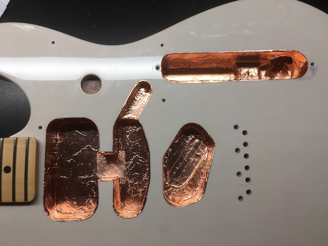
All cavities now shielded. I made sure to bring the shielding up over so that a bit of it was hanging over the edge. This way, when the shielded pickguard got installed, it would come into contact with the cavity shielding thereby providing a path to ground. By the way, I used copper tape that had conductive adhesive.


Here is a shot of the shielded pickguard in progress and completed. In the completed photo, you can clearly see the outline of the original shielding. It basically covers up just the pickup cavities. Because I was having the problem with the static noise when playing, I figured I'd have to shield the entire pickguard. My first attempt was to ground the original shield and that did NOT fix it. This solution, however, worked like a charm.


Time to start wiring...


I had pre-wired the control plate earlier. I forgot to take pictures as I went along so here is the finished product. Notice the switch is quite different from the original. This is an Oak-Grigsby 5-Way 2-Pole "Super-Switch" that I ordered from ToneShapers. The way I wanted the Telecaster wired couldn't be done with the original switch.


Here is the wiring diagram I used. Unfortunately, I found the image on Pintrest via a Google search so I don't know who drew up it up.


Here are closeups of the "Super-Switch" and the Bourns 250K Pots. By the way, those Bourns pots are really great. They have a very smooth action when turning. I found them to be superior to the CTS pots I pulled out of this guitar. I ordered the pots and the caps from Arrow Electronics.


Guitar all wired up and put back together.


All strung up and ready to go.


I also did a complete fret level and dress which I didn't bother to document. I posted a similar project in my "Dressing Some Frets" blog on that in 2016. Although the frets were in good shape, I felt that a level was in order and I also wanted to create a "fall-away" past the 12th fret. I know that isn't documented in the 2016 blog but there are lots of videos and information about how to do that online. 

This was a very satisfying project to do. There is something oddly therapeutic about installing copper shielding...LoL. Anyway, the guitar is now completely shielded and although it probably didn't require it with noiseless pickups, I don't intend on keeping those pickups in there. I have a stock MiM Standard Telecaster that sounds fantastic. This one doesn't even come close. For whatever reason, I just don't like these Noiseless pickups. I had a Strat with them as well and I didn't like it then either. I ended up selling it. Just my personal preference. I've heard lots of people like these P-Ups. 

Well...that wraps up this Blog. I must say the guitar plays really nicely. I just hope I can replicate that magical Tele sound with different pickups and still get a bit of that Strat quack in the 2 and 4 positions.

Sunday, 8 January 2017

Boss FS-6 Power Mod

I was getting frustrated with having to yank the 1/4" cable from my Boss FS-6 foot switch every time I was done playing. I decided to embark on what I thought was going to be a simple project to add a power switch to the unit. Unfortunately, my 2 hour project ended being more like 10 hours. I'm documenting it here so anyone out there decides to do this, they'll hopefully avoid my mistakes.

Here goes...

Although I started out wanting to add a power switch only, I decided to add a switching DC power jack as well. This is what I bought...but...oops...


The DC power jack I bought won't work. All Boss pedals (almost all pedals for that matter) use a negative center tip and the chassis of this jack is conductive and since it will end up being positive, I can't mount it to the foot switch chassis assuming it will be used for ground. Back to the store for a plastic DC barrel jack...


I decided on a flush mount DC barrel jack thinking it would look nicer...another mistake. After mounting it, the jack sits too far inside the case of the FS-6 so that when you try to assemble the 2 halves back together, it won't close properly. Buy this DC barrel jack instead please and save yourself a whole lot of headache.


Ok...I also had a lot of problems even with this DC barrel jack and after much trial and error, I finally figured out what I needed to do to make everything fit and for the case to close properly. Using a sharp X-Acto knife, cut off the edges of the jack as follows...


As you can see, I shaved off 3 sides. By the way, the image of the cut DC barrel jack is upside down. You want to install it into the chassis with the center pin connector facing up. The center pin connector is the one that looks different than the other two. The top is is required so that the PC board of the foot switch will clear the jack. One side needs to be shaved so the polarity switch is accessible and the other probably wasn't necessary but I wasn't sure if it would clear the side wall of the foot switch chassis so I did it anyway.

Ok...now that we got that all out of the way, here is what I did to get everything going. First off...the schematic. The S, B, and T in the diagram represents the 3 connectors of the DC barrel jack.


The way this is wired up, there is a master On/Off switch but if you unplug the power from the DC jack, the battery will still supply voltage to the foot switch. Here are pictures of the wiring test. You can see in the first picture, the voltage is supplied by the barrel jack at the top of the image producing 8.94vdc. The next image shows the jack unplugged and now running off the battery which is producing 9.61vdc.


Ok...time to start drilling and mounting everything. I used a step drill bit to drill the back of the foot switch chassis. Unfortunately, I was so wrapped up in the process, I forgot to take pictures of the drilled out chassis before I assembled it. I was too lazy to take everything apart after. Hopefully, you get the idea by looking at the assembled images.


In put the power jack on the left side (if you're looking at the rear of the foot switch) and the switch on the right. You have to measure the center of the DC side perfectly. There isn't a lot of clearance on the back face of the foot switch chassis after you drill out the correct size hole. In fact, you'll notice that the barrel jack is slightly elongated and not a perfect circle. I took a rat tail file and filed the hole a little bigger on the top and bottom sides and left as much metal as I could on the side.

As you can see from the picture, I put some shrink tubing on the DC jack since the wires would be in close proximity. I didn't want an accidental short. I also used some duct tape to tape down the wiring to try to keep it neat.


Here it is after I put everything back together.


Power switch OFF


Power switch ON and voltage supplied by wall wart.


Running off battery


Conclusion.

If I had to do it all over again. I would probably not bother with the DC power jack. It really was a pain to install that thing.